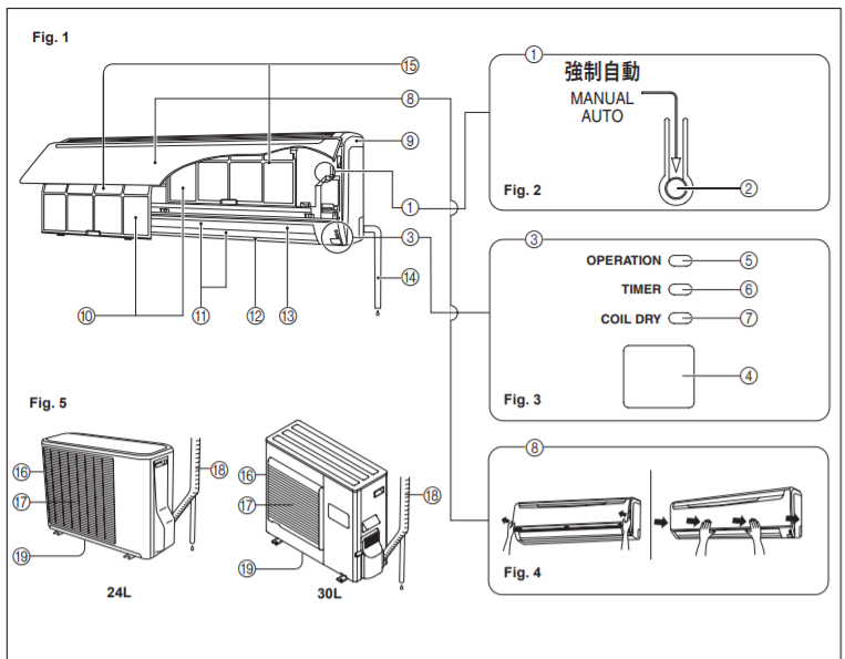
Fig. 1 Indoor Unit
1 Operating Control Panel (Fig. 2)
2 MANUAL AUTO button
When kept on pressing the MANUAL AUTO button for more than 10 seconds, the forced cooling operation will start.
The forced cooling operation is used at the time of installation. Only for authorized service personnel’s use.
When the forced cooling operation starts by any chance, press the START/STOP button to stop the operation.
3 Indicator (Fig. 3)
4 Remote Control Signal Receiver
5 OPERATION Indicator Lamp (red)
6 TIMER Indicator Lamp (green)
If the TIMER indicator lamp flashes when the timer is operating, it indicates that a fault has occurred with the timer setting
7 COIL DRY Indicator Lamp (orange)
8 Intake Grille (Fig. 4)
9 Front Panel
10 Air Filter
- Air Flow Direction Louver B Power Diffuser
- Right-Left Louver (behind Air Flow Direction Louver)
- Drain Hose
- Air Cleaning Filter
Fig. 5 Outdoor Unit
F – Intake Port
G – Outlet Port
H – Pipe Unit
I – Drain port (bottom)
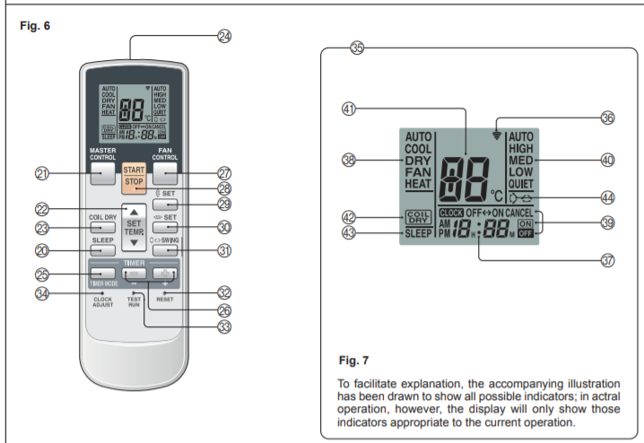
Fig. 6 Remote Controller
J – SLEEP button
K – MASTER CONTROL button
L – SET TEMP. button ( / )
M – COIL DRY button
N – Signal Transmitter
O – TIMER MODE button
P – TIMER SET ( / ) button
Q – FAN CONTROL button
R – START/STOP button
S – SET button (Vertical)
T – SET button (Horizontal)
U – SWING button
V – RESET button
W – TEST RUN button
X – CLOCK ADJUST button
Y – Remote Controller Display (Fig. 7)
Z – Transmit Indicator
[ Clock Display
\ Operating Mode Display ] Timer Mode Display ` Fan Speed Display
a Temperature SET Display
b COIL DRY Display
c SLEEP Display d SWING Display